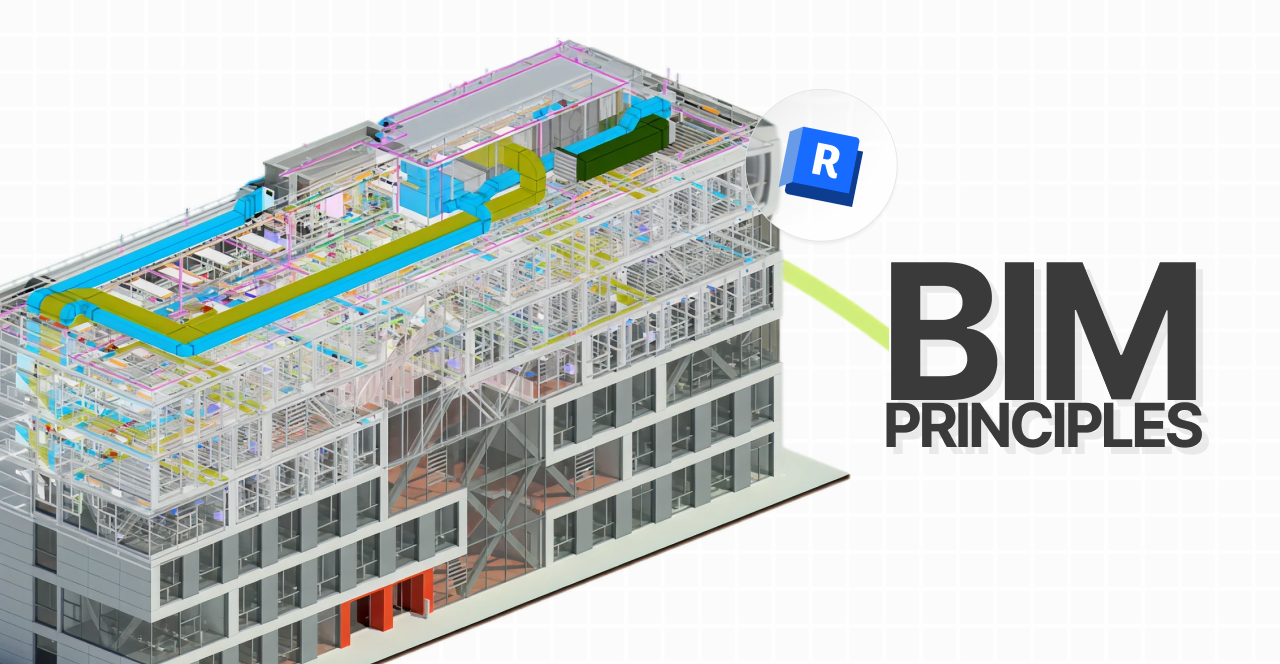
If you’re an architect, engineer, or interior designer working with BIM (Building Information Modeling), you’ve probably come across parametric families in Revit.
To understand parametric families, let’s start with what “families” actually are.
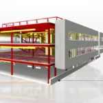
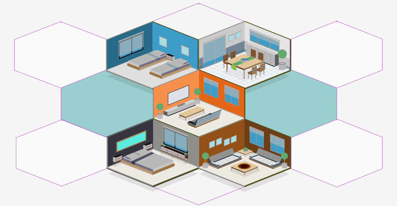
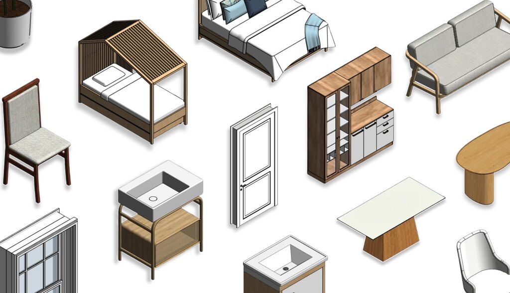
They are basic “building blocks” of Revit, like doors, windows, furniture, and other model components.
Parametrization,which is the key advantage of parametric families, defines the specific data behavior of each one..
Want to learn more about how parametric families work? Keep reading, this guide will walk you through everything you need to know.
Enjoy your reading.
What are parametric families in Revit?
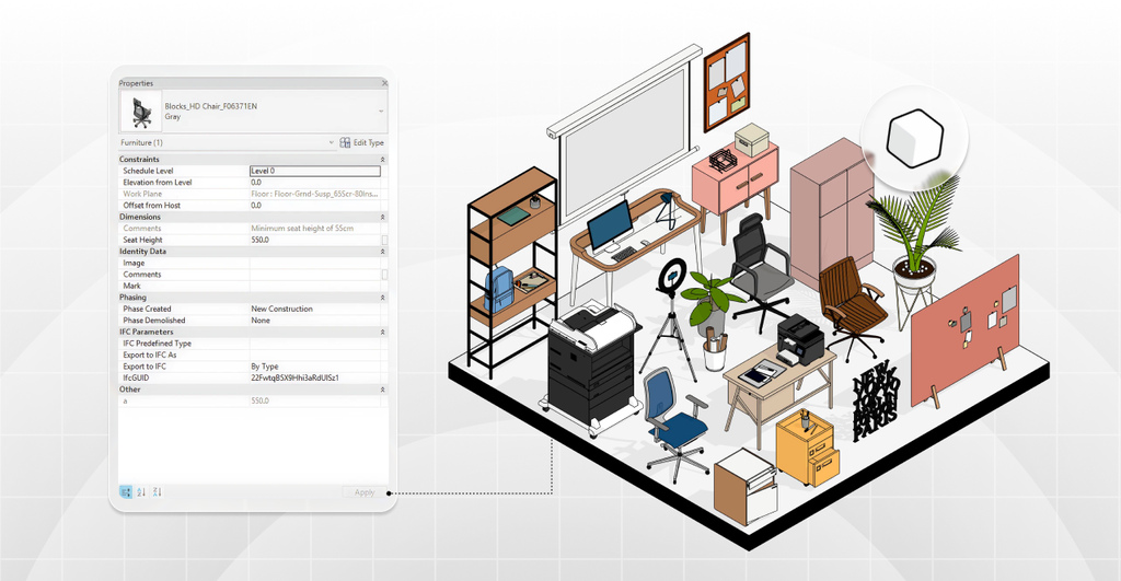
Parametric families are intelligent Revit components with adjustable parameters.
In other words, you can modify the BIM object’s dimensions, materials, or settings to match your design intent.
Each parametric family behaves like a smart object that automatically updates itself, no need to redraw from scratch.
Unlike AutoCAD or SketchUp, Revit objects carry not only geometry but also information and rules that control their behavior.
That means Revit families are rich in data, fully defined by parameters that describe how they react within a model.
However, there are also non-parametric families, whose data doesn’t automatically adapt to design changes.

Bárbara Pavanello
CEO | Blocks®
“In everyday AEC practice, parametric families in Revit are like having a smart shortcut always at hand. You change one parameter, and that’s it — your entire model updates automatically, with no rework or headaches. This speeds up your workflow, keeps everything consistent, and ensures accurate quantities. However, when a parameter is set as instance, only the instance you’re editing updates automatically — the others stay the same. It’s like having a ‘built-in assistant’ inside Revit handling the repetitive work while you focus on what really matters: creating, solving, and delivering better projects with less effort.”
Why use parametric families in Revit?
Simply put, parametric families make modeling faster and smarter in Revit.
Because they let you adjust properties instantly, Revit can coordinate those updates far more efficiently than with static elements.
So, any change you make is reflected across all instances, without breaking your model.
For example, if you update the width of a parametric window type, every window of that type updates automatically in plans, sections, and 3D views.
In short, parametric families exist to simplify your workflow and automate repetitive design tasks.
How to parametrize a family in Revit
Now that we understand what parametrization means in Revit, let’s put that knowledge into practice and learn how to create a parametric family step by step.
We’ll walk you through how to build your own parametric family , in case you’re curious to try it yourself.
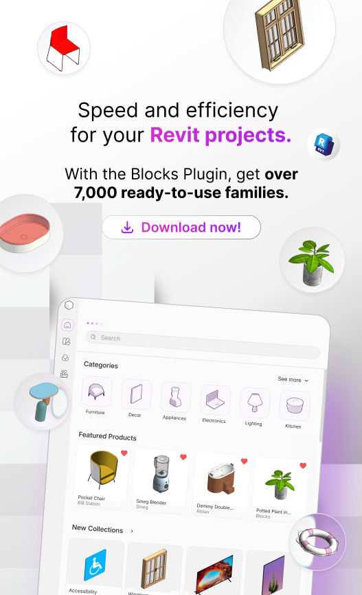
However, if you’d rather skip the manual work, you can always rely on the Blocks Plugin, which already includes over 7,000 ready-to-use parametric families.
So, ready to learn how to create one? Let ‘s get started!
1. Start the family editor
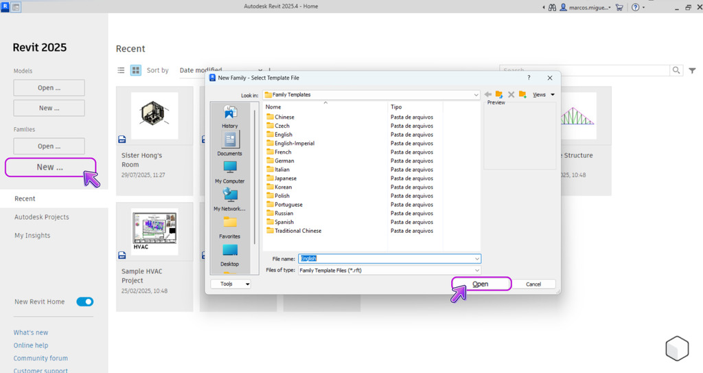
Everything begins with a Family Template in Revit.
From your open project, go to File → New → Family. Revit will ask you to select the right template.
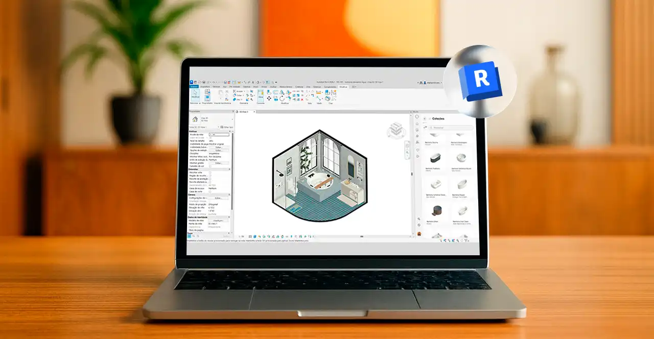
Once opened, you’ll be in the Family Editor, it looks similar to the project workspace but includes tools dedicated to component modeling.
First, check the default reference planes. They define the family’s origin and help you position geometry accurately.
You’ll use them to establish dimension limits and reference points for your parameters.
Now you’re ready to build your parametric framework.
2. Define reference planes
Reference planes are the foundation of a well-constructed parametric family (think of them as a structural guide for your object).
To add one, go to Create < Reference Plane, and give each plane a clear name to stay organized. We recommend naming each plane to keep your family organized.
Autodesk® itself suggests building a structure of reference planes and lines first, and then aligning your geometry to them.
That’s because when you lock and align geometry to reference planes, any change to those planes automatically updates the geometry as well.
Note: Take your time with this step, position all the planes you’ll need to define width, height, depth, and any other key references in your design.
3. Create geometry
With your reference plane structure in place, it’s time to start modeling the family geometry.
In the Create tab, select the right tools for the job, the most common ones are Extrusion, Blend, Revolve, Sweep, Swept Blend, and Void Forms.
Then, sketch the desired geometry profile directly on the correct work plane.
While sketching, use Align and Lock to lock the sketch lines to the reference planes.
For example, if you draw a rectangle for a tabletop extrusion, align each side of the rectangle with its corresponding reference plane and click the Lock icon to fix it.
That way, if the reference planes move closer together or farther apart (in other words, if the width or depth changes), the extrusion sketch will move with them — automatically resizing the tabletop.
Finish the sketch and set the extrusion depth as needed. Repeat the process for the remaining parts of your object.
Always ask yourself: “Will this dimension or position need to be parametric?” If yes, use reference planes and alignments. If not, it can stay fixed.
4. Add parameters
With the geometry in place, it’s time to make your family truly parametric. It’s time to add parameters.
In the Family Editor, go to the Modify (or Create) tab and click Family Types.
In the window that opens, you’ll see a list of parameters, initially empty, except for a few default ones depending on the template.
Click Add (or New Parameter). Give the parameter a name, choose its data type, choose the group where it will be organized, and define whether it’s a Type or Instance parameter.
- Type parameter: applies to all instances of the same family type. If you change its value, every element of that type in the project updates automatically. Use this for standardized dimensions, for example, Door 32” vs. Door 36” as two separate types.
- Instance parameter: can vary for each instance placed in the project. This means you can have two objects of the same type with different values for that parameter. Use it when you need case-by-case flexibility without creating multiple types, for example, an adjustable length unique to each instance.
After creating your parameter, link it to a dimension or property.
For example, select the dimension that represents your family’s width (the one aligned with your reference planes) and, in the options bar, instead of keeping a fixed value, associate it with the “Width” parameter you just created.
The distance between those planes is now controlled by the parameter. Repeat this process for height, depth, or as many parameters as you need.
It’s important to note that parameters are anchored to reference planes, since they serve as the foundational structure for your family’s geometry.
5. Visibility settings
Not every geometry element in a family should appear in every view or situation.
That’s why adjusting visibility settings is key to producing professional-quality families.
For example, you might have detailed 3D elements that you don’t want to show in a floor plan, or symbolic 2D components that should appear only in section views.
To configure this, select a geometry element in the Family Editor, open its Properties, and click Visibility (or Visibility/Detail Level Settings).
There, you can define which views the element will appear in, such as plan, elevation, or left/right views, and at which detail levels (coarse, medium, or fine).
This way, you can simplify your family’s appearance at a 1:100 scale and display more detail at a 1:20 scale.
Another powerful feature is the Yes/No visibility parameter. You can create a Boolean parameter (usually an instance parameter) — for example, Show Handle — and assign it to the visibility of a specific element (like a door handle).
Then, when you load the family into a project, you’ll see a checkbox that lets you easily show or hide that element.
6. Save and load the family
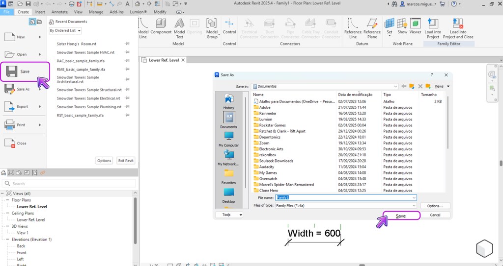
With everything ready and tested, it’s time to save your family and bring it into your project.
Go to File → Save As → Family, give it a name, and click Load into Project — Revit will insert the new family into the active project.
Alternatively, you can close the Family Editor and, inside your project, go to Insert → Load Family and select the .rfa file you saved earlier.
Once loaded, the family will appear in the Project Browser, under the category you assigned when you created it (based on the chosen template).
You can drag and drop it into your model or use the appropriate placement tool — for example, Component for furniture or generic models, Door for door families, and so on, depending on the category.
Place an instance in your project, and if you’ve set up different types, switch between them in the Properties palette and watch the magic happen. The geometry should update automatically according to the defined parameters.
If you need to make adjustments, simply right-click the family in the Project Browser and select Edit to return to the Family Editor.
Make your changes, then reload the family into your project to overwrite the previous version.
That’s it! You’ve just created and used your first parametric family in Revit. 🎉
As you can see, it’s a process that requires planning and attention to detail, but the boost in productivity makes it totally worth it.
Where to get ready-made parametric families in Revit?
After seeing how much effort it takes to create a family from scratch, you might be wondering: is there an easier way to get high-quality parametric families?
The good news is — yes! Imagine having all of that in a single platform fully integrated with Revit.
The Blocks Plugin brings together over 7,000 parametric families in one place.
Picture this: you can insert any piece of furniture, lighting fixtures, equipment, or decorative elements into your project with a single click, no more digging through websites for that perfect model.
Instead of spending hours (or even days) downloading individual families, you can rely on a unified library right inside Revit.
Our collection keeps growing, with weekly updates that bring new themed sets — from contemporary furniture and decor to landscaping and equipment.
And the best part is: many of these families are available for free through the plugin’s Free plan.
Interested? Download the Blocks Plugin for free and see for yourself how powerful it is to have a parametric BIM library right at your fingertips.
Conclusion
Mastering parametric families in Revit is a key step for any professional or student looking to stand out in the BIM world.
As we’ve seen, these intelligent families help you design more efficient projects, while reducing rework and unlocking countless creative possibilities.
With parametric families integrated into your workflow, you gain greater control over every element, allowing you to fine-tune them to meet your project’s needs.
Remember: practice makes perfect, so don’t hesitate to open Revit and start experimenting. 😉
And of course, be sure to check out the Blocks Plugin to make your projects even faster with ready-to-use, high-quality components.
Enjoyed this article? Stay tuned to the Blocks Blog for more tips, tutorials, and insights on BIM, Revit, architecture, and design.